Imagine you were to get to see some amazing old sculpture. A real museum piece. The Venus De Milo. You get your eyes on the Venus De Milo. You’re looking at it and you want to steal it. There is a museum curator watching you, there are security guards, other museum patrons, etc. There is absolutely no way they will let you do that. Also, the statue has to weigh close to 2 tons. You aren’t going to be hauling it out on your back, but you can take a picture of it. Maybe a lot of pictures. Maybe a lot of pictures with a camera that can capture depth and minor variations in the surface of the marble. Pits, cracks, dust, all of it. You and your camera take a quick buzz around the Venus snapping shots the whole way, and bug out.
Now that you have all of this information in images, it should be possible for you to start with a blank approximation of the Venus De Milo and recreate all of those details. Will it be exactly the same? No, of course not. Could you deceive the other art thieves with it? Will it look convincing enough from a distance to get you into all of the art thief parties? Only one way to find out.
Now since I do most of my art stealing digitally and figuratively, I set up a tool to make that high detail image capture easier.
You see, when you set up digital 3D models for use in real time applications, that is exactly what you do. You take heavy, detailed, high resolution art and you crush it down to something that a computer can draw to a screen 30, 60, 90, or 120 times a second. The better you can steal that detail and pack it up into images, the more convincing the final result will be.
Some stuff I have been working on required nice seamless tiles of high detailed fakery. There are tools and techniques that let you do this, but most of them are clumsy, slow, or expensive. I spent some time this past week to fix that.
Just to be clear, I haven’t made anything revolutionary here. This isn’t some sort of stand alone tool. I put together the equivalent of a carpenters jig. A simple tool that helps you to do a more complicated job more easily.
If that sort of thing doesn’t seem up your alley you can bail now. It’s okay, I get it. I’m going to break down how I set up one of my tools in Blender.
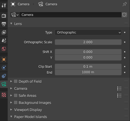
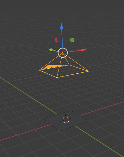
Let’s start with the camera. I set up a single orthographic camera right above my work area and set the orthographic scale to 2. I set it to 2 because I will be using a 2x2 plane as the extents of my texture. You can set it to whatever size you like, but I find this works for me.
Under Render Properties I set the display device in the color management dropdown to None. This prevents visual color crunching from alternate color profiles.
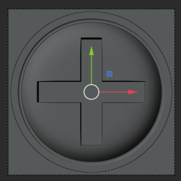
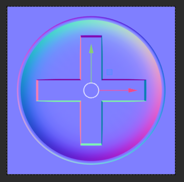
This is what the same screw head looks like when I apply a normal shader to it. The normal shader encodes, in rgb pixels, the way that light would bounce off of a surface if it were 3 dimensional rather than 2 dimensional. The colors represent the deviation from the surface normal (perpendicular to the face). So it looks bumpy without actually being bumpy.
 |  |
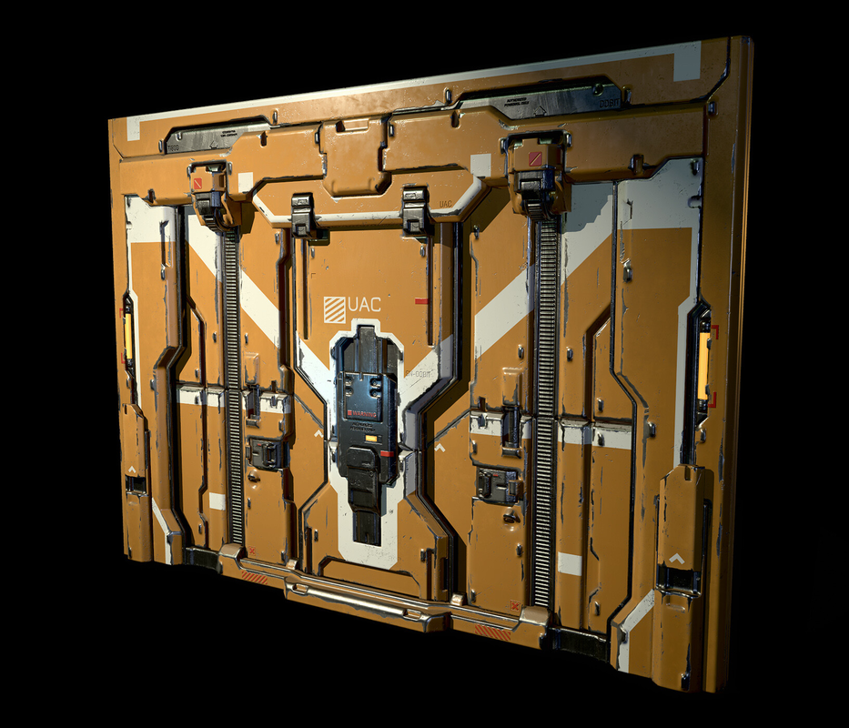 | 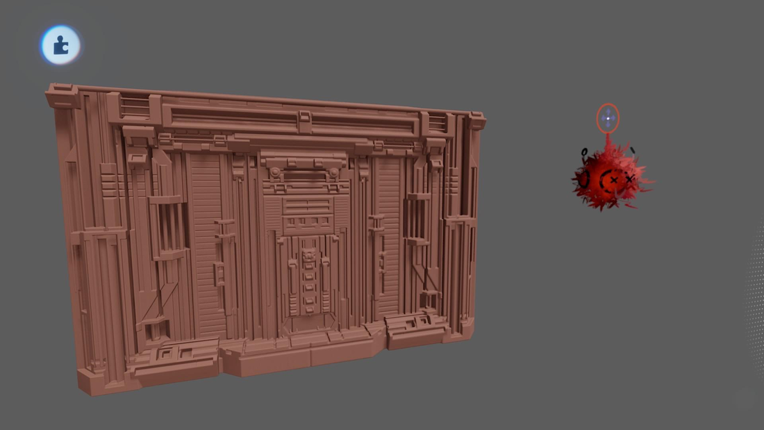 |
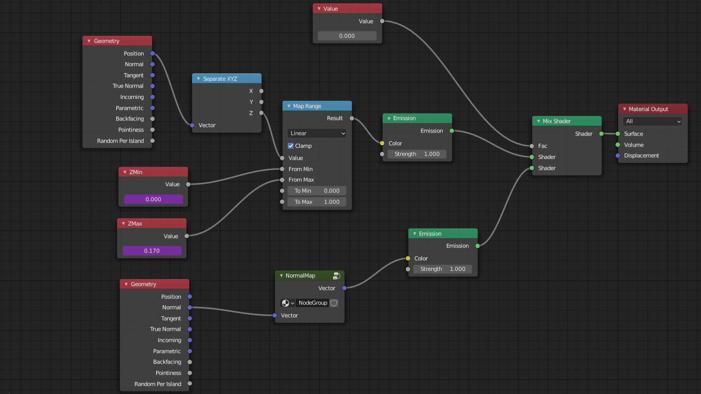
I’m passing all of these into an emission shader because emission is a pure representation of the output color we are looking for. No lights or shadows mucking things up. I get the position of the geometry that has the material applied to it with the geometry node and pass that to a Separate XYZ node. We are only interested in the Z position so I take that and pass it to a Map Range node. I want to take the distance between my two measurement objects, my ZMin and ZMax, and remap that distance to a 0-1 scale. This will give us a pure black to pure white gradient. I pipe that result into the emission shader and then pipe that to the material output. In this case I go though my mix shader for switching from depth to normal, but I wouldn’t need to.
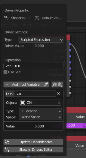
You might notice that the ZMin and ZMax are purple. That is because those Value nodes contain a float driven by the Z position of my two measurement objects.
You can drive damn near any value with any other in blender just by right clicking on the input field and clicking on add driver. It’s something I don’t do nearly enough of but it’s very handy.
This is what’s in that node group.
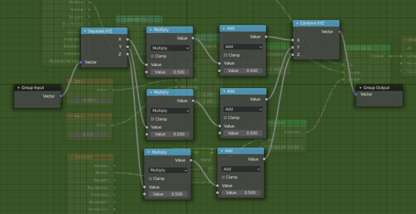
I take the new colors, put them into an emission shader and we’re almost done.
Now for the real reason I put together this setup. Baking.
The common workflow for this sort of setup is to make an empty image texture and ‘bake’ the detail from your screwheads or whatever into that image texture. Then you save that out to a file and you’re done. Great, right?.
No, it blows. Baking is slow, uses a different render path than I’m using to display the results, and sometimes contains artifacts and issues that you can’t see before the bake is done. I had depth and normal maps where two adjacent pixels that should have had a lot of contrast between each other turn into a mushy mess when baking.
To get the result out of the new method I use EEVEE (Blenders real time rendering engine) in the camera viewport and I press this.
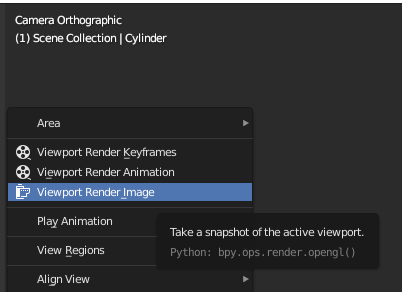
Then it’s a click of Image - Save As to save the OpenEXR file and I’m done. I think that, in the future, I could set up a python script to run through the whole process for any maps I have to export and it could be a one click type of process. For now though, this works, and more important, it works so much better than baking.
Of course this works for flat surface details. Stealing the detail off the Venus De Milo might take a bit more work, but I have some ideas about that I might sort out one day.